Test Pre-Compliance
Radiated Emissions
Pre-Compliance Radiated Emissions testing evaluates a design for the unintentional release of energy via an electromagnetic field. These fields can be generated by problems with layout, grounding, enclosures, cabling, and other structures that may be acting as unintentional antennas across the frequency band. Ultimately, the goal is to make sure the design will pass a full compliance test once it is ready for production. Radiated emissions are radiated through the air, so there are two main ways to test for them:
1)A near field probe helps us visualize potential sources of error by only picking up signals close to the probe head and in the correct orientation. This helps us to identify parts of our board or product that our actually emitting the problem signals. Using a calibrated far field antenna an engineer can closely approximate a full compliance test creating reliable measurements on the amplitude of the signals in question. Comparing these power levels to the relevant compliance limits enables an engineer to understand how much headroom they have in their design and ultimately whether or not it will pass a compliance test.
2)One other aspect of radiated emissions is cable emissions testing. Connected data cables such as USB or HDMI can act as antennas as well. Current clamps and probes as well as amplifiers may be needed to fully characterize these emissions. Having these cables attached and powered up can make a significant difference in near and far field measurements. Cabling should always be considered when testing emissions.
RIGOL supports engineers by providing instruments, probes, and software programs that can adjust for calibrated antennas and varying emissions limits in a variety of radiated testing. RIGOL helps customers capture, adjust, and analyze radiated emissions data to speed a project’s time to market by identifying potential problems before they require extensive rework that extends the design cycle.
Learn more:
RIGOL’s EMI Pre-Compliance Application Note
This application note covers hints and tips for implementation of precompliance steps to help lower the cost of full compliance EMC testing. It also features a series of documents that have practical use details for EMC testing.
Conducted Emissions
Pre-Compliance Conducted Emissions is how engineers test for unintended power that gets coupled or transmitted back into the power line. The focus these regulations is to make sure the power line remains ‘clean’ and that other devices on the circuit and the power grid won’t be effected.
To isolate the measurements from the power line noise and provide a stable impedance for these measurements a LISN or Line Impedance Stabilization Network is used. Additional hardware such as attenuators and transient limiters may be used to optimize the measurement system to test a certain device. Pre-Compliance testing of conducted emissions helps engineers avoid costly errors in their power supply design or procurement. For engineers selecting an off the shelf AC-DC power adaptor for their product, a basic conducted emissions test can make procurement decisions easier and eliminate surprises at the compliance lab.
RIGOL Spectrum Analyzers and S1210 EMI Pre-Compliance software can be configured to adjust for correction factors from LISNs, attenuators, and other devices. This enables engineers to confidently take their product to a compliance lab with high confidence of passing the first time.
Learn more:
Pre-Compliance Conducted Emissions
Learn more about proper test techniques for performing precompliance conducted emissions testing using a spectrum analyzer including test setup, common error sources, and instrument configuration.
Immunity
Immunity tests a product’s ability to function when in close proximity to electromagnetic fields. There are two main types of signals used to test a product’s immunity:
1) Modulated waves – Often AM modulated waves across the frequency ranges of interest. These waves test the product’s ability to ignore power at frequencies that may be coupled into the device over time. These signals may effect a product’s communication, reliability, or logic.
2) Pulsed and Burst waves – These transients affect a device immediately and can cause a number of power and functional issues. Electrostatic discharge or ESD testing is a common type of transient immunity testing. These fast pulses can have different effects on a product and need to be considered as a potential source of reliability and functional issues.
In addition to RIGOL’s other Pre-Compliance instrumentation, immunity testing requires an RF source to generate high power modulated waves. Other types of equipment may need to be purchased for transient generation.
Learn more:
Immunity
How to use an RF generator to test radiated immunity and susceptibility.
EMC precompliance test flow
• Step 1: Conducted emission testing and improvement
Conducted emissions often go hand in hand with radiated emissions. Reducing
conducted emissions usually also reduces radiated emissions
Required equipment: spectrum analyzer + LISN
• Step 2: Radiated emission testing
Check the radiated spectrum for spurious with excessive level
Required equipment: spectrum analyzer + TEM cell
• Step 3: Localize the source(s) of excessive radiation and improvement
Scan the board with near field probes to track down the sources of radiation
and apply countermeasures
Required equipment: spectrum analyzer + EMC near field probes
• Step 4: RF immunity testing
Check the product for RF immunity issues
Required equipment: RF signal gemerator + RF power amplifier + TEM cell
• Step 5: Localize the origin of immunity issues and improvement
Feed the near field probes with an RF signal and scan the board to track
down the origin of immunity issues; apply countermeasures
Required equipment: RF signal gemerator + (RF power amplifier) + TEM cell
HARDWARE SETUP
Conducted emission testing

Setup for conducted emission testing of DC-powered equipment (e.g. CISPR25)
The DUT shall be isolated and elevated from the groundplane. The spectrum
analyzer shall measure the conducted emissions on both supply lines. The RF output of
the unused LISN shall be terminated with 50 Ohm. If the power return line is less
than200 mm, a setupwith a single LISN is sufficient. For the exact details of the set up
and for the limits of conducted emissions refer to the CISPR 25 or relevant
applicable standard.
Conducted emission testing
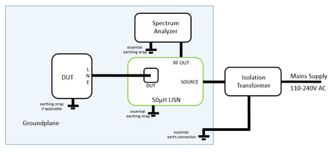
Setup for conducted emission testing of AC-powered equipment (e.g.CISPR16)
The DUT shall be isolated and elevated from the groundplane. The spectrum
analyzer shall measure the conducted emissions on both line and neutral.
The value of the parallel combination of the capacitors is 12μF from line and neutral to ground.
This causes around 0.75A flowing into the earth connection and would trip the ground fault switch.
Hence, an insulation transformer is required and good grounding is essential for safety.
For the exact details of the set up and for the limits of conducted emissions
refer to the CISPR 16 or other relevant applicable standard. A built in limiter or
a limiter between the LISN RF output and spectrum analyzer is essential for the protection of the equipment.
Radiated emission testing
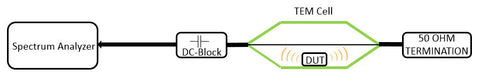
Terminate any of the two ports of the TEM cell with the 50Ω load, connect the DC-Block to the other port and connect it to the input of the spectrum analyzer. Place the DUT under the septum and power it on.
Monitor the radiated spectrum.
As a rule of thumb, given that the PCB is positioned not much higher than 1-2cm above the bottom wall, any spurious with amplitudes higher than 40dμV may potentially cause a failed compliance test.
Use compliance tested DUTs and the corresponding test reports as a reference for measurements in the TEM cell.
Localizing the source of emissions

Localize the source of unwanted emissions on the DUT PCB using near field probes and a spectrum analyzer.
Implement counter measures and re-test the DUT inside the TEM cell to verify if the modifications result in a reduction of the radiated emissions
RF immunity testing
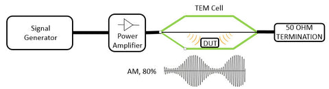
Terminate any of the two ports of the TEM cell with the 50Ω load, and connect the signal generator + power amplifier to the other port. The signal needs to be AM modulated (80%) according to most standards. The power of the signal has to be chosen according to the required field strength. Place the DUT under the septum and power it on.
Sweep the signal generator and monitor the DUT for RF immunity issues.
The picture above shows a minimum setup. Inserting a directional coupler with connected RF power meter in between power amplifier and TEM cell would be of advantage to monitor power levels.
Localizing the origin of immunity issues
Localize the section on the DUT PCB which is susceptible to RF.
Use a power amplifier only, if the output power of the Signal generator alone was not sufficient to reproduce the immunity issue.
Implement counter measures and re-test the DUT inside the TEM cell to verify if the modifications removed the RF immunity issues.